Tractor Trailer Geometries for Computational Fluid Dynamics
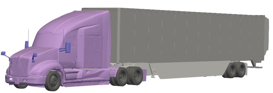
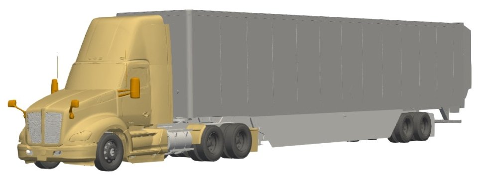
Tractor Trailer Geometrics for Computational Fluid Dynamics is a method to model air flow around shapes such as planes, vehicles, and trucks. By solving flow equations in a computational setting (i.e. CFD software), CFD can simulate wind resistance (drag) on a vehicle traveling down the road. CFD is commonly used by engineers in optimizing and visualizing air flow with vehicle design features for different duty cycles and road conditions. While different manufacturers have vehicle geometries for their own developmental purposes, EPA is providing detailed heavy-duty tractor-trailer geometries to enable the performance of CFD simulations for research and to facilitate improvements in CFD-related work.
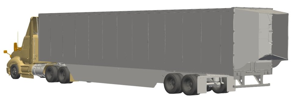
A modern sleeper tractor and day cab were scanned, along with a 53’ box trailer, to create a set of high-fidelity tractor-trailer geometries. While small modifications were incorporated into the scans to protect intellectual property, the primary features of the exterior, undercarriage, tires, wheels, and engine compartment are maintained to provide representative images for modeling. Additionally, multiple aerodynamic devices for the trailer were scanned and may be incorporated to demonstrate different levels of aerodynamic drag.


In a CFD simulation, the software examines a truck model’s movement in accordance with its properties, such as velocity, pressure, and temperature. These properties are used to calculate the truck model’s coefficient of drag multiplied by the vehicle’s frontal area. The lower the total, the lower the energy (e.g., fuel) needed to move the truck forward through air. Because CFD is using mathematical calculations, it can have low test-to-test variability compared to full scale truck testing; however, the settings used in CFD can significantly influence results. Consequently, having data from other test methods for comparison to CFD results is particularly important.
The most representative results will come from closely simulating on-road conditions and using a high-fidelity digital truck geometry. The files below contain the STL files for two tractor geometries and a dry box trailer with three aerodynamic devices. (STL stands for Standard Triangle Language or Standard Tessellation Language, which are languages used for 3D imaging and printing.)
- Sleeper Tractor STL Files (zip) (April 2023)
- Day Cab Tractor STL Files (zip) (April 2023)
- 53-foot Box Trailer STL Files (with removable skirt and rear device) (zip) (April 2023)
Using CFD Simulation for SmartWay Trailer Device Verification
Currently, EPA accepts CFD results as a secondary or supplemental method in a verification application. Manufacturers who choose to submit CFD results in verification should consult with EPA first and follow the guidelines in 40 CFR 1037.532: Using computational fluid dynamics to calculate drag area (CdA). The table below summarizes the parameters from the SAE J2966 standard for CFD simulations:
| Simulation Settings | SAE J2966 (2013) | SAE J2966 (2021) |
|---|---|---|
| Surface Elements | 6 million | Greater than 6 million |
| Volume Grid Size | 50 million | 60 million |
| Domain Size | Use the equation for calculating domain size | Same as 2013 std |
| Domain Boundary Conditions | Velocity inlet and zero-gradient pressure outlet. Domain sides and top can be modeled with opening, symmetry, or free-slip (sliding) wall boundary conditions to minimize any far-field influence on the model for on-road simulations. | Same as 2013 std |
| Simulation Model | Model should match the physical article; may include open grill, the cooling package, and detailed under hood components, where applicable. Pressure drop in porous media (cores) in the cooling package can be represented with Darcy’s Law or polynomial function. | Same as 2013 std |
| Cooling Fan Model | It is recommended to consider the effect of the cooling fan. Stationary fan geometry or porous jump boundary conditions are acceptable; modeling the fan as a rotating (or free-spinning) component recommended. | Same as 2013 std |
| Y+ Range | Less than 300; 30-100 recommended | Same as 2013 std |
| Number of flow passes | 5 convective flow passes or more | 4 convective flow passes or more |
SAE International Ground Vehicle Standard, “Guidelines for Aerodynamic Assessment of Medium and Heavy Commercial Ground Vehicles Using Computational Fluid Dynamics,” SAE standard J2966, Rev June 2021 and Sept 2013.
